Standard Punch Press
Sheet metal bending machines to meet the highest demands
Standard Punch Press
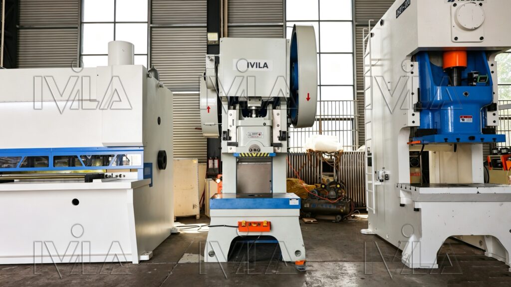
A mechanical punch press operates by storing energy in a flywheel driven by an electric motor. Through a clutch and crankshaft system, the rotational motion is converted into a vertical reciprocating motion of the ram, which drives the punch into the die to process sheet metal.
Key characteristics:
- High operating speed
- Stable and repeatable motion
- Suitable for continuous production
technology
Frame Structure
The frame structure is the core load-bearing system of a mechanical punch press. It determines the machine’s rigidity, precision, vibration resistance, and overall service life. During stamping operations, all punching forces are transmitted through the frame, making it one of the most critical components of the machine.
Oil Pump & Motor
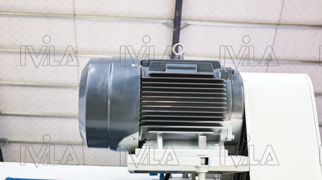
In mechanical punch presses and hydraulic-driven industrial systems, the oil pump and motor unit is a critical power source that directly affects machine stability, efficiency, and service life. Customized solutions are widely used to match different tonnage, stroke speed, and working conditions.
High Precision Backgauge
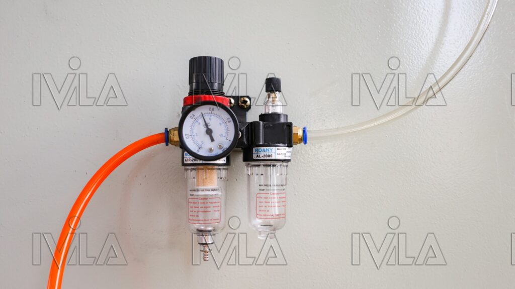
In a mechanical punch press, the air counterbalance system (balance bar / air cylinder system) is used to support and balance the weight of the ram (slide) and upper die. It is an important auxiliary system that improves machine stability, safety, and stamping performance.
Detail Display
Machine Showcase
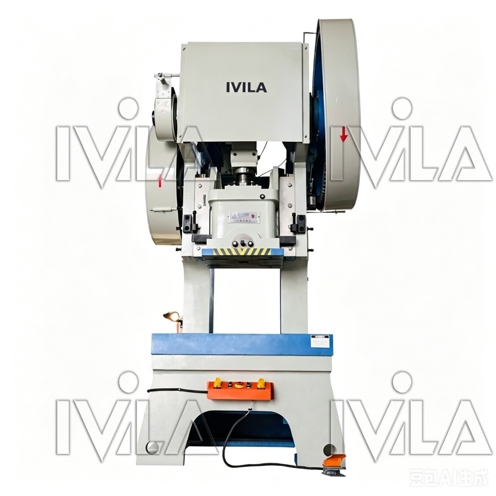
Customized mechanical press services provide solutions that specifically design and optimize press equipment—covering structure, tonnage, configuration, safety systems, and control methods—based on a client's specific industry applications, production processes, and automation requirements. The core objective is to better align the equipment with actual production needs, thereby enhancing efficiency, precision, and stability.
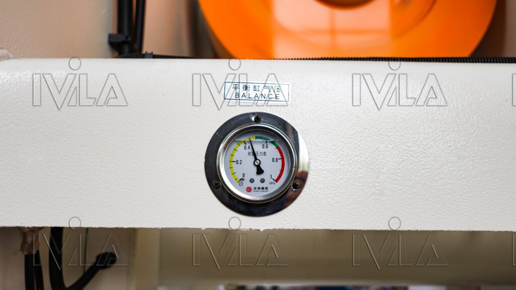
Pressure Gauge in a Mechanical Punch Press
A pressure gauge is an essential monitoring instrument used in mechanical punch presses (and related hydraulic or pneumatic systems) to measure and display system pressure in real time. It ensures the machine operates within safe and designed pressure limits.
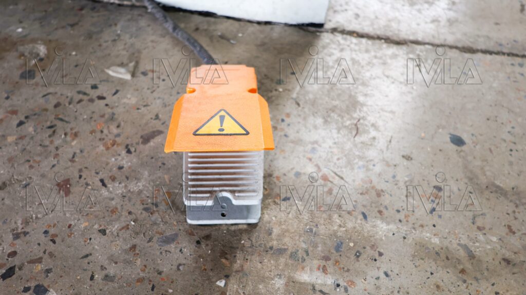
Foot switch
In mechanical power presses, a foot switch is typically used to control: Single-stroke operation Jog/inch mode (on some models) Automatic cycle start (in automatic feeding systems)
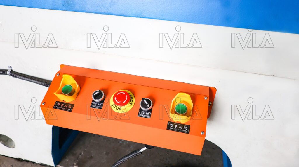
Push-button switch
A push-button switch is a key operator control component used in a mechanical punch press to start, stop, and control machine functions through electrical signals. It is part of the machine’s control panel and works together with the press control system, clutch, and safety circuits.
Technical Parameters
| Name | J23- | J23- | J23- | J23- | J23- | J21- | J21- | |
| 16T | 25T | 40T | 63T | 80T | 100T | 125T | ||
| Nominal Pressure (kN) | 160 | 250 | 400 | 630 | 800 | 1000 | 1250 | |
| Nominal Pressure Stroke (mm) | 5 | 5 | 6 | 6 | 8 | 9 | 10 | |
| Slider Stroke (mm) | 60 | 70 | 100 | 100 | 120 | 130 | 140 | |
| Slider Stroke Rate (cycles/min) | 110 | 70 | 55 | 60 | 50 | 45 | 45 | |
| Maximum Sealing Height (mm) | 220 | 260 | 320 | 330 | 380 | 380 | 400 | |
| Sealing Height Adjustment Range (mm) | 50 | 60 | 80 | 80 | 100 | 100 | 100 | |
| Distance from Slider Centerline to Bed (mm) | 180 | 190 | 230 | 240 | 260 | 310 | 340 | |
| Worktable Dimensions | Front-to-Back (mm) | 300 | 320 | 400 | 450 | 480 | 590 | 660 |
| Left-to-Right (mm) | 450 | 530 | 650 | 710 | 750 | 890 | 980 | |
| Worktable Blanking Hole Dimensions | Front-to-Back (mm) | 130 | 140 | 170 | 180 | 220 | 240 | 260 |
| Left-to-Right (mm) | 200 | 220 | 240 | 260 | 340 | 360 | 400 | |
| Diameter (mm) | 120 | 130 | 160 | 170 | 190 | 200 | 210 | |
| Overall Dimensions of Slider Base | Front-to-Back (mm) | 130 | 170 | 220 | 230 | 240 | 280 | 360 |
| Left-to-Right (mm) | 220 | 250 | 300 | 340 | 370 | 410 | 480 | |
| Die Shank Hole Dimensions | Diameter (mm) | 40 | 40 | 50 | 50 | 60 | 60 | 70 |
| Depth (mm) | 60 | 60 | 70 | 70 | 80 | 80 | 90 | |
| Distance Between the Two Columns of the Machine Bed (mm) | 170 | 210 | 260 | 280 | 300 | 340 | 370 | |
| Clearance Between the Worktable and the Guide Rails (mm) | 250 | 290 | 340 | 350 | 380 | 400 | 430 | |
| Shim Thickness (mm) | 45 | 50 | 80 | 80 | 90 | 100 | 110 | |
| Tilt Angle of the Machine Bed (degrees) | 30 | 25 | 25 | 25 | 25 | / | / | |
| Motor | Power (kilowatts) | 1.5 | 2.2 | 4 | 5.5 | 7.5 | 7.5 | 11 |
| Rotational Speed (revolutions per minute) | 1410 | 1440 | 1440 | 1440 | 1440 | 1440 | 1460 | |
| Dimensions | Length (front to back) (millimeters) | 1100 | 1200 | 1500 | 1600 | 1750 | 1800 | 1890 |
| Width (left to right) (millimeters) | 780 | 900 | 1100 | 1150 | 1300 | 1400 | 1500 | |
| Height (millimeters) | 1800 | 2050 | 2400 | 2480 | 2600 | 2680 | 2800 | |
More Details
Products Related Categories
Video
Watch video below to learn more details